The main purpose of the calculation of the slurry pipe and trough hydraulic transmission is to estimate the critical flow rate, head loss, or over-flow section. At present, there are many such formulas, but most of them are empirical or semi-empirical formulas derived under a certain condition, which lacks wide applicability. Some formulas need to be further verified even with their applicable conditions. Now we will introduce the applicable scope of some commonly used calculation formulas in China and the problems existing in the use.
(1) Pressure delivery A BC Knorroz formula a Calculation formula

W———solid volume per unit volume of the slurry, kg/m 3 ;
S———the weight per unit volume of the liquid in the slurry, kg/m 3 ;
D l ———critical pipe diameter, m;
β———The correction coefficient of the slurry flow rate, calculated by the following formula:

From the data calculated by the above formula, the unit head loss can be determined by the following formula:
i=δ k i 0 (6)
Where i—the unit head loss of the transporting slurry, mm;
δ k ———slurry density, g/cm 3 or t/m 3 ;
δ g ———solid density, t/m 3 ;
i 0 ———Water head loss equal to the slurry flow rate [next]

D j ———calculate the pipe diameter (ie the pipe diameter actually selected), m;
υ j ———calculate the flow rate (ie the selected flow rate corresponding to the actual diameter of the pipe), m/s;
g———gravitational acceleration, 9.81m/s 2 ;
λ———the resistance coefficient reflecting the smoothness of the pipe wall;

b Applicable conditions The BC Knoroz formula is derived from the solid density δ g = 2.70 ton / m 3 . The test shows that the larger the δ g value, the farther the calculated value of the critical flow rate deviates from the test value. Moreover, the critical flow rate will increase with the increase of the consistency of the slurry, which is completely inconsistent with the normal law of the high-concentration slurry. Therefore, this formula is not applicable to the high-concentration slurry transportation. In addition, if the flow rate is too small, the critical flow rate will be too small. It is generally considered that this formula is only applicable to low-concentration slurries with a particle size of less than 0.4 mm with δ g <3 ton/ m3 and δ k <1.25 ton/ m3 .
B A.II. Euphen's formula a Calculation formula

Wherein d 90 , d 10 ——— less than 90% of the particle size, 10% of the particle size, mm;
Q k ———slurry flow, m 3 /s;
W———the free sedimentation velocity of particles with average particle size, m/s;
D l ———critical pipe diameter, m;
δ k ——— pulp density, t/m 3 ;
i———Unit head loss of conveying slurry, m water column/meter;
i 0 ———Unit head loss of conveying clean water, m water column/meter;

D j ———calculate the pipe diameter, m; when the pipe diameter D is greater than or equal to the critical pipe diameter D l , take D j = D l ; when D < D l , take D j = D;
υ j ———calculate the flow rate (ie the flow rate corresponding to the calculated pipe diameter), m/s;
g———Gravity acceleration, equal to 9.81m/s 2 ;
λ———the drag coefficient, calculated as follows:
Introduction
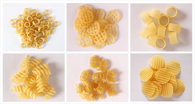
The line adopt rice flour, wheat flour, corn starch and other food additives as the main material, through mixer, single screw extrusion, dryer to produce a various of pasta in different shapes, colors.
Some shapes such as crispy pea, shell, screw, wheel, tube etc which are popular in the market. If want make tube shape, the pulling and cutting machine is also necessary.
Flow Chart
Mixing materials - Extruding - Cutting - Drying - Cooling
Technical Parameter

Machine Photo

Sample Photo

Macaroni Extruding Line,Pasta Machines Manufacturer,Macaroni Manufacturing Machine,Automatic Pasta Macaroni Making Machine
Jinan Darin Machinery Co., Ltd. , https://www.globaldarin.com
